Introduction
The goal of this article will be to provide you with the required steps to build a Virtual eXtensible LAN Ethernet VPN (VXLAN EVPN) fabric using the Cisco NXOS-9000v.
The topology will be built using various protocols, so before we dive in let's look at the various protocols, some background and how they fit together.
Note: The NXOS version used throughout this guide is 7.0(3)I7(1).
Background
VXLAN (Virtual eXtensible LAN) is a network virtualization overlay protocol that was created to address some of the challenges seen within traditional networks, such as,
-
Addressing VLAN scalability issues due to being limited to 4094 VLANs by adding a 24-bit segment ID and increasing the number of available IDs to 16 million.
-
Flexible placement of multi-tenant segments throughout the data center. Tenant workload can be placed across physical segments in the data center.[1]
-
Traffic can be routed over an L3 fabric removing the requirement for STP/legacy L2 fabrics.
VXLAN works via the use of VTEP's (Virtual Tunnel Endpoint). VTEP's encapsulate the original frame (aka 'MAC-in-UDP', see Figure 1). The packet is then sent to the remote VTEP over the underlying network. The remote VTEP then removes the encapsulation headers and forwards the original frame onto its destination.

Figure 1 - VXLAN header.
VXLAN natively operates on a flood-n-learn based mechanism, in which BUM (Broadcast, Unknown Unicast, Multicast) traffic in a given VXLAN network is sent to every VTEP that has membership in that network. There are two ways to send such traffic - IP multicast or via Head-end Replication (unicast).[2]
Flood-and-learn allows each peer VTEP to perform the following.
- End-host learning by decapsulating the packet and performing MAC learning via the inner frame.
- Peer discovery via the inner source MAC to outer source IP (source VTEP).
From this information reverse traffic can be unicasted back towards the previously learnt peer.
To minimize the extent to which flooding needs to occur, EVPN was defined by IETF as the standards-based control plane for VXLAN overlays.[3] EVPN is an extension (i.e address family) of MP-BGP (Multi-Protocol BGP) that allows for the MAC and IP of end-hosts behind VXLAN VTEPs to be advertised and exchanged.
One key point to note, even with an EVPN control plane, VXLAN flood and learn will still be used, however greatly minimized. This is because EVPN will exchange known end-hosts, i.e. end-hosts that are populated within the destination MAC table. Only if the host is unknown will F&L be performed.
Topology
The topology we will be building will be based around 2 layers - the underlay and the overlay.
The Underlay
The underlay will provide connectivity (aka a fabric) between each spine and leaf. This connectivity will later be used by the overlay for BGP-EVPN and VXLAN (i.e VTEP-to-VTEP communication). The protocols we will configure within the underlay are:
- OSPF (IGP) - Provides loopback reachability between all nodes (leaf/spine).
- PIM (IP Multicast) - For VXLAN flood-and-learn.
The Overlay
The overlay will send encapsulated traffic over the underlay network. The protocols we will configure within the overlay are:
- VXLAN - Encapsulates/decapsulates traffic between VTEPs i.e. the dataplane.
- BGP-EVPN - Operates as the control plane to distribute end-host and VTEP reachability information.
Our topology will also be configured to use Distributed IP Anycast Gateway and ARP Suppression/

Figure 2 - Topology Overview.
NXOSv-9000 Caveats
Limitations
There are a few limitations with the version of NXOSv-9000 we will be using. Therefore the following will not be configured within this fabric:
- Jumbo frames on the L2 links (i.e edge ports)
- PIM BiDir
- BFD
Commands
Various commands are different between the NXOSv-9000 to standard NXOS. The key command to note is show system internal l2fwder mac which should be used instead of show mac address-table.
Underlay
The first part to our topology will be to build the underlay fabric. This will be based upon the following:
- Spine and Leaf topology to provide equidistant reachability and scalability.
- An OSPF IGP to provide connectivity between loopbacks.
- IP Multicast PIM-SM to reduce the flood-and-learn traffic upon the network.
- Unnumbered interfaces (sourced from lo0). This will allow for easier (templated) configurations.
- Lo0 reachability across the fabric for BGP peering.
- Jumbo frames upon all links to reduce ethernet header overhead.
Let's begin ...
Links
First of all we will configure each of the links within the underlay. The configuration will:
- Turn each link to Layer 3.
- Enable the link.
- Enable jumbo frames.
Configuration
Spines/Leafs (ALL)
interface Ethernet1/1-X
  no switchport
  mtu 9216
  no shutdown
Validation
The validation will be to check that each of the interfaces shows as connected.
nx-osv9000-1# show int status
--------------------------------------------------------------------------------
Port          Name               Status    Vlan      Duplex  Speed   Type
--------------------------------------------------------------------------------
mgmt0         OOB Management     connected routed    full    1000    --
Eth1/1        to nx-osv9000-3    connected routed    full    1000    10g
Eth1/2        to nx-osv9000-4    connected routed    full    1000    10g
Eth1/3        to nx-osv9000-5    connected routed    full    1000    10g
Eth1/4        to nx-osv9000-6    connected routed    full    1000    10g
OSPF
Next we configure OSPF as the IGP for connectivity between loopbacks. This will be based upon a single OSPF area, also each OSPF interface will be configured as a Point-to-Point network type in order to reduce the amount of LSA's required on the network, and also within the LSDB. Details of the loopback addresses are shown below:

Figure 3 - OSPF Underlay.
Configuration
Spines (ALL)
feature ospf

router ospf OSPF_UNDERLAY_NET
  log-adjacency-changes

interface Ethernet1/1-4
  medium p2p
  ip unnumbered loopback0
  ip router ospf OSPF_UNDERLAY_NET area 0.0.0.0

interface loopback0
  description Loopback
  ip address 192.168.0.X/32
  ip router ospf OSPF_UNDERLAY_NET area 0.0.0.0
Leafs (ALL)
feature ospf

router ospf OSPF_UNDERLAY_NET
  log-adjacency-changes

interface Ethernet1/1-2
  medium p2p
  ip unnumbered loopback0
  ip router ospf OSPF_UNDERLAY_NET area 0.0.0.0

interface loopback0
  description Loopback
  ip address 192.168.0.X/32
  ip router ospf OSPF_UNDERLAY_NET area 0.0.0.0
Validation
The validation is pretty straight forward. We check the OSPF neighbor states, the RIB for the OSPF learned routes and perform a quick ping to confirm Lo0 connectivity.
nx-osv9000-1# show ip ospf neighbors
 OSPF Process ID OSPF_UNDERLAY_NET VRF default
 Total number of neighbors: 4
 Neighbor ID     Pri State            Up Time  Address         Interface
 192.168.0.3       1 FULL/ -          00:35:35 192.168.0.3     Eth1/1
 192.168.0.4       1 FULL/ -          00:35:36 192.168.0.4     Eth1/2
 192.168.0.5       1 FULL/ -          00:35:36 192.168.0.5     Eth1/3
 192.168.0.6       1 FULL/ -          00:35:35 192.168.0.6     Eth1/4

nx-osv9000-1# show ip route ospf-OSPF_UNDERLAY_NET
IP Route Table for VRF "default"
'*' denotes best ucast next-hop
'**' denotes best mcast next-hop
'[x/y]' denotes [preference/metric]
'%<string>' in via output denotes VRF <string>

192.168.0.2/32, ubest/mbest: 4/0
    *via 192.168.0.3, Eth1/1, [110/81], 00:33:29, ospf-OSPF_UNDERLAY_NET, intra
    *via 192.168.0.4, Eth1/2, [110/81], 00:33:29, ospf-OSPF_UNDERLAY_NET, intra
    *via 192.168.0.5, Eth1/3, [110/81], 00:33:29, ospf-OSPF_UNDERLAY_NET, intra
    *via 192.168.0.6, Eth1/4, [110/81], 00:33:29, ospf-OSPF_UNDERLAY_NET, intra
192.168.0.3/32, ubest/mbest: 1/0
    *via 192.168.0.3, Eth1/1, [110/41], 00:35:20, ospf-OSPF_UNDERLAY_NET, intra
     via 192.168.0.3, Eth1/1, [250/0], 00:35:09, am
192.168.0.4/32, ubest/mbest: 1/0
    *via 192.168.0.4, Eth1/2, [110/41], 00:35:21, ospf-OSPF_UNDERLAY_NET, intra
     via 192.168.0.4, Eth1/2, [250/0], 00:35:07, am
192.168.0.5/32, ubest/mbest: 1/0
    *via 192.168.0.5, Eth1/3, [110/41], 00:35:21, ospf-OSPF_UNDERLAY_NET, intra
     via 192.168.0.5, Eth1/3, [250/0], 00:35:11, am
192.168.0.6/32, ubest/mbest: 1/0
    *via 192.168.0.6, Eth1/4, [110/41], 00:35:18, ospf-OSPF_UNDERLAY_NET, intra
     via 192.168.0.6, Eth1/4, [250/0], 00:35:18, am

nx-osv9000-1# ping 192.168.0.5 interval 1 count 2
PING 192.168.0.5 (192.168.0.5): 56 data bytes
64 bytes from 192.168.0.5: icmp_seq=0 ttl=254 time=3.09 ms
64 bytes from 192.168.0.5: icmp_seq=1 ttl=254 time=3.029 ms
PIM
PIM is configured for the VXLAN Flood and Learn mechanism. Our multicast configuration will be based upon the following:
- PIM Sparse-Mode.
- Anycast RP to provide RP (Rendezvous Point) redundancy.
- Each Spine configured as an RP (Rendezvous Point).

Figure 4 - Underlay Multicast PIM.
Configuration
Spines (ALL)
feature pim

ip pim rp-address 1.2.3.4 group-list 224.0.0.0/4
ip pim ssm range 232.0.0.0/8
ip pim anycast-rp 1.2.3.4 192.168.0.1
ip pim anycast-rp 1.2.3.4 192.168.0.2

interface loopback1
  ip address 1.2.3.4/32
  ip router ospf OSPF_UNDERLAY_NET area 0.0.0.0
  ip pim sparse-mode

interface loopback0
  ip pim sparse-mode

int Ethernet1/1-4
  ip pim sparse-mode
Leafs (ALL)
feature pim

ip pim rp-address 1.2.3.4 group-list 224.0.0.0/4
ip pim ssm range 232.0.0.0/8

interface loopback0
  ip pim sparse-mode

interface Ethernet1/1
  ip pim sparse-mode

interface Ethernet1/2
  ip pim sparse-mode
Validation
To validate we check that PIM is successfully enabled on the interfaces and that the Anycast RP is operational.
nx-osv9000-1# show ip pim interface brief
PIM Interface Status for VRF "default"
Interface            IP Address      PIM DR Address  Neighbor  Border
                                                     Count     Interface
Ethernet1/1          192.168.0.1     192.168.0.3     1         no
Ethernet1/2          192.168.0.1     192.168.0.4     1         no
Ethernet1/3          192.168.0.1     192.168.0.5     1         no
Ethernet1/4          192.168.0.1     192.168.0.6     1         no
loopback0            192.168.0.1     192.168.0.1     0         no
loopback1            1.2.3.4         1.2.3.4         0         no

nx-osv9000-1# show ip pim rp
PIM RP Status Information for VRF "default"
BSR disabled
Auto-RP disabled
BSR RP Candidate policy: None
BSR RP policy: None
Auto-RP Announce policy: None
Auto-RP Discovery policy: None

Anycast-RP 1.2.3.4 members:
  192.168.0.1*  192.168.0.2

RP: 1.2.3.4*, (0),
 uptime: 01:56:56   priority: 255,
 RP-source: (local),
 group ranges:
 224.0.0.0/4
For more information about PIM, see /what-is-pim-protocol-independent-multicast
Network Virtual Endpoint (NVE)
The NVE (Network Virtual Endpoint) is a logical interface where the encapsulation and de-encapsulation occurs.
We will configure a single NVE upon each leaf only. In addition, the NVE will use a source address of Lo0.
Configuration
Leafs (ALL)
interface nve1
  no shutdown
  host-reachability protocol bgp
  source-interface loopback0
Verification
nx-osv9000-3# show interface nve 1
nve1 is up
admin state is up,  Hardware: NVE
  MTU 9216 bytes
  Encapsulation VXLAN
  Auto-mdix is turned off
  RX
    ucast: 0 pkts, 0 bytes - mcast: 0 pkts, 0 bytes
  TX
    ucast: 0 pkts, 0 bytes - mcast: 0 pkts, 0 bytes
Overlay
MP-BGP EVPN
As previously mentioned EVPN will be used as the control plane for the VXLAN data plane; distributing the address information of our end-hosts (IP, MAC) so that the VXLAN flood-and-learn behaviour can be reduced.
The BGP-EVPN control plane will be based on the following:
- iBGP based adjacencies.
- Each spine acting as a BGP route reflector.
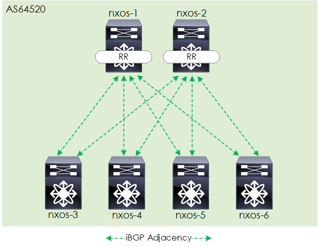
Figure 5 - EVPN BGP Overlay.
Configuration
Spines (ALL)
nv overlay evpn
feature bgp
feature fabric forwarding
feature interface-vlan
feature vn-segment-vlan-based
feature nv overlay

router bgp 64520
  log-neighbor-changes
  address-family ipv4 unicast
  address-family l2vpn evpn
    retain route-target all
  template peer VXLAN_LEAF
    remote-as 64520
    update-source loopback0
    address-family ipv4 unicast
      send-community extended
      route-reflector-client
      soft-reconfiguration inbound
    address-family l2vpn evpn
      send-community
      send-community extended
      route-reflector-client
  neighbor 192.168.0.3
    inherit peer VXLAN_LEAF
  neighbor 192.168.0.4
    inherit peer VXLAN_LEAF
  neighbor 192.168.0.5
    inherit peer VXLAN_LEAF
  neighbor 192.168.0.6
    inherit peer VXLAN_LEAF
Leafs (ALL)
nv overlay evpn
feature bgp
feature fabric forwarding
feature interface-vlan
feature vn-segment-vlan-based
feature nv overlay

router bgp 64520
  log-neighbor-changes
  address-family ipv4 unicast
  address-family l2vpn evpn
  template peer VXLAN_SPINE
    remote-as 64520
    update-source loopback0
    address-family ipv4 unicast
      send-community extended
      soft-reconfiguration inbound
    address-family l2vpn evpn
      send-community
      send-community extended
  neighbor 192.168.0.1
    inherit peer VXLAN_SPINE
  neighbor 192.168.0.2
    inherit peer VXLAN_SPINE
Verification
For the verification, we first ensure that the address family is enabled. Then we check that the BGP adjacencies are established. If this was not the case then the state would be shown (in other words the state is only shown when the peering is not fully established).
nx-osv9000-3# show ip bgp neighbors 192.168.0.1 | inc "Address family L2VPN EVPN"
  Address family L2VPN EVPN: advertised received
nx-osv9000-3# show bgp l2vpn evpn summary
BGP summary information for VRF default, address family L2VPN EVPN
BGP router identifier 192.168.0.3, local AS number 64520
BGP table version is 24, L2VPN EVPN config peers 2, capable peers 2
5 network entries and 10 paths using 1424 bytes of memory
BGP attribute entries [10/1600], BGP AS path entries [0/0]
BGP community entries [0/0], BGP cluster list entries [6/24]

Neighbor        V    AS MsgRcvd MsgSent   TblVer  InQ OutQ Up/Down  State/PfxRcd
192.168.0.1     4     1      58      55       24    0    0 00:46:30 3
192.168.0.2     4     1      58      55       24    0    0 00:46:10 3
Enhancements
Now that we have our underlay running, and an EVPN control plane functional we will add some small enhancements to our topology.
Distributed IP Anycast Gateway
The distributed IP anycast gateway is a feature that allows you to configure the default gateway of a subnet across multiple ToR's using the same IP and MAC address. This solves the issue of traffic tromboning, seen in traditional networks by ensuring the end-host's default gateway is at its closest point. This, in turn, provides optimal traffic forwarding within the fabric.
Configuration
To configure this feature the anycast gateway MAC is defined and the feature added to the relevant SVI interface. Like so:
fabric forwarding anycast-gateway-mac 0000.0010.0999

interface vlan <vlan_id>
  fabric forwarding mode anycast-gateway
Validation
To validate we will checking the fabric forwarding mode. Like so:
nx-osv9000-3# show fabric forwarding internal topo-info | grep Anycast
Forward Mode                   : Anycast Gateway
ARP Suppression
ARP suppression is a feature that reduces the flooding of ARP request broadcasts upon the network. ARP suppression is enabled on a per VNI basis. Once enabled, VTEPs maintain an ARP suppression cache table for known IP hosts and their associated MAC addresses in the VNI segment. [4]
At the point an end-host sends an ARP request, the local VTEP intercepts the ARP request and checks its ARP suppression cache for the IP. At this point, one of 2 things will happen:
- Hit - If there is a match within the cache - the local VTEP sends an ARP response on behalf of the remote end host.
- Miss - If the local VTEP doesn't have the ARP-resolved IP address in its ARP suppression table, it floods the ARP request to the other VTEPs in the VNI.[5]
Configuration
The configuration is pretty straightforward, we enable the tcam region and then add the suppress-arp command to each VNI that we want to suppress ARP upon. Like so:
hardware access-list tcam region arp-ether 256

interface nve1
  !
  member vni <vni>
    suppress-arp
Note: You may find when configuring the tcam region that you receive an error much like this:
Warning: Please configure TCAM region for Ingress ARP-Ether ACL for ARP suppression to work.
If so you can edit one of the other regions to make space:
hardware access-list tcam region vpc-convergence 0
Validation
To validate we can check the arp suppression cache, after issuing some pings from our end hosts. Within this table, we will check for the entries learnt, shown under the R flag.
nx-osv9000-3# show ip arp suppression-cache detail

Flags: + - Adjacencies synced via CFSoE
       L - Local Adjacency
       R - Remote Adjacency
       L2 - Learnt over L2 interface
       PS - Added via L2RIB, Peer Sync
       RO - Dervied from L2RIB Peer Sync Entry

Ip Address      Age      Mac Address    Vlan Physical-ifindex    Flags    Remote Vtep Addrs

10.10.1.1       00:00:57 fa16.3e94.17d1   10 Ethernet1/3         L
10.10.1.2       02:02:38 fa16.3e0f.521e   10 (null)              R        192.168.0.5
L2 Bridging/L3 Routing
With the EVPN VXLAN fabric built, we can now turn our attention to the configuration required to perform L2 bridging (L2VNI) and L3 routing (L3VNI) from our end hosts.
For the VNI numbers and for further clarity on how our topology will look once configured, see below:

Figure 6 - L2VNI/L3VNI's.
Once configured, the traffic flows (intra-VNI and inter-VNI), will look like the below:

Figure 7 - L2VNI/L3VNI Traffic Flows.
L2 Bridging
L2 bridging aka the bridging of traffic (L2 frames) between end-hosts on the same VNI will be achieved via the L2VNI.
Configuration
Leafs (NXOS-3 + NXOS-5)
fabric forwarding anycast-gateway-mac 0000.0011.1234

vlan 10
  vn-segment 100010

interface Vlan10
  no shutdown
  ip address 10.10.1.254/24
  fabric forwarding mode anycast-gateway

interface nve1
  !
  member vni 100010
    suppress-arp
    mcast-group 224.1.1.192

evpn
  vni 100010 l2
    rd auto
    route-target import auto
    route-target export auto
Leafs (NXOS-4 and NXOS-6)
fabric forwarding anycast-gateway-mac 0000.0011.1234

vlan 20
  vn-segment 100020

interface Vlan20
  no shutdown
  ip address 10.20.1.254/24
  fabric forwarding mode anycast-gateway

interface nve1
  !
  member vni 100020
    suppress-arp
    mcast-group 224.1.1.192

evpn
  vni 100020 l2
    rd auto
    route-target import auto
    route-target export auto
Validation
To validate we can view the EVPN routes learnt against one of the L2VNI's. Once done we can check connectivity.
nx-osv9000-3# show bgp l2vpn evpn  vni-id 100010
BGP routing table information for VRF default, address family L2VPN EVPN
BGP table version is 5644, Local Router ID is 192.168.0.3
Status: s-suppressed, x-deleted, S-stale, d-dampened, h-history, *-valid, >-best
Path type: i-internal, e-external, c-confed, l-local, a-aggregate, r-redist, I-injected
Origin codes: i - IGP, e - EGP, ? - incomplete, | - multipath, & - backup

   Network            Next Hop            Metric     LocPrf     Weight Path
Route Distinguisher: 192.168.0.3:32777    (L2VNI 100010)
*>i[2]:[0]:[0]:[48]:[fa16.3e0f.521e]:[0]:[0.0.0.0]/216
                      192.168.0.5                       100          0 i
*>l[2]:[0]:[0]:[48]:[fa16.3e94.17d1]:[0]:[0.0.0.0]/216
                      192.168.0.3                       100      32768 i
*>i[2]:[0]:[0]:[48]:[fa16.3e0f.521e]:[32]:[10.10.1.2]/272
                      192.168.0.5                       100          0 i
*>l[2]:[0]:[0]:[48]:[fa16.3e94.17d1]:[32]:[10.10.1.1]/272
                      192.168.0.3                       100      32768 i
cisco@server-1:~$ sudo mtr --report 10.10.1.2
Start: Wed Jan 16 22:23:41 2019
HOST: server-1                    Loss%   Snt   Last   Avg  Best  Wrst StDev
  1.|-- 10.10.1.2                  0.0%    10   27.0  18.0  13.7  27.0   4.0
L3 Routing
In order to forward traffic between VNIs, we will configure an L3VNI. Traffic will be routed to the L3 VNI within the leaf when destined for another VNI. The packet will then be sent (bridged) over the L3 VNI to the remote node, where the traffic will again be routed to the destination VNI. In other words, the traffic is routed, bridged and then routed.
Below shows an example of a capture packet from one of the leaf to spine uplinks. As you can see the packet is sent over the L3VNI (VNI 100999).

Figure 8 - ICMP Packet between VNIs over L3VNI
Configuration
Leafs (ALL)
vlan 999
  vn-segment 100999

vrf context TENANT1
  vni 100999
  rd auto
  address-family ipv4 unicast
    route-target both auto
    route-target both auto evpn

interface Vlan999
  no shutdown
  vrf member TENANT1
  ip forward

interface nve1
  !
  member vni 100999 associate-vrf
Leafs (NXOS-3 + NXOS-5)
router bgp 64520
  vrf TENANT1
    log-neighbor-changes
    address-family ipv4 unicast
      network 10.10.1.0/24
      advertise l2vpn evpn
Leafs (NXOS-4 + NXOS-6)
router bgp 64520
  vrf TENANT1
    log-neighbor-changes
    address-family ipv4 unicast
      network 10.20.1.0/24
      advertise l2vpn evpn
Validation
To validate we can view the EVPN routes learnt against the L3VNI. Once done we can check connectivity.
nx-osv9000-3# show bgp l2vpn evpn  vni-id 100999
BGP routing table information for VRF default, address family L2VPN EVPN
BGP table version is 5644, Local Router ID is 192.168.0.3
Status: s-suppressed, x-deleted, S-stale, d-dampened, h-history, *-valid, >-best
Path type: i-internal, e-external, c-confed, l-local, a-aggregate, r-redist, I-injected
Origin codes: i - IGP, e - EGP, ? - incomplete, | - multipath, & - backup

   Network            Next Hop            Metric     LocPrf     Weight Path
Route Distinguisher: 192.168.0.3:3    (L3VNI 100999)
*>i[2]:[0]:[0]:[48]:[fa16.3e0f.521e]:[32]:[10.10.1.2]/272
                      192.168.0.5                       100          0 i
*>i[2]:[0]:[0]:[48]:[fa16.3e34.693a]:[32]:[10.20.1.2]/272
                      192.168.0.6                       100          0 i
*>i[2]:[0]:[0]:[48]:[fa16.3ec5.7233]:[32]:[10.20.1.1]/272
                      192.168.0.4                       100          0 i
* i[5]:[0]:[0]:[24]:[10.10.1.0]:[0.0.0.0]/224
                      192.168.0.5                       100          0 i
*>l                   192.168.0.3                       100      32768 i
* i[5]:[0]:[0]:[24]:[10.20.1.0]:[0.0.0.0]/224
                      192.168.0.6                       100          0 i
*>i                   192.168.0.4                       100          0 i
cisco@server-1:~$ sudo mtr --report 10.20.1.1
Start: Wed Jan 16 22:28:20 2019
HOST: server-1                    Loss%   Snt   Last   Avg  Best  Wrst StDev
  1.|-- 10.10.1.254                0.0%    10    4.7   4.6   3.5   5.7   0.6
  2.|-- 10.20.1.254                0.0%    10   22.6  14.3  11.4  22.6   3.6
  3.|-- 10.20.1.1                  0.0%    10   17.4  19.0  15.6  27.1   3.1
Outro
Phew! We made it. As you can see there is a lot to configure, with many layers and protocols to take into account. I hope you enjoyed this tutorial, you can find all the final configurations, plus VIRL topology file at:
https://github.com/rickdonato/networking-labs/tree/master/labs/nxos9k-evpn-vxlan
References
"[ VXLAN ]: Are VXLANs Really the Future of Data Center Networks ...." 1 Dec. 2017, https://www.serro.com/vxlan-vxlan-really-future-data-center-networks/. Accessed 4 Jan. 2019. ↩︎
"Cisco Programmable Fabric with VXLAN BGP EVPN Configuration ...." 18 Jul. 2018, https://www.cisco.com/c/en/us/td/docs/switches/datacenter/pf/configuration/guide/b-pf-configuration/Introducing-Cisco-Programmable-Fabric-VXLAN-EVPN.html. Accessed 11 Jan. 2019. ↩︎
"Deploy a VXLAN Network with an MP-BGP EVPN Control Plane - Cisco." https://www.cisco.com/c/en/us/products/collateral/switches/nexus-7000-series-switches/white-paper-c11-735015.pdf. Accessed 4 Jan. 2019. ↩︎
"EVPN MPLS with ARP suppression - Cisco Community." 1 Sep. 2017, https://community.cisco.com/t5/xr-os-and-platforms/evpn-mpls-with-arp-suppression/td-p/3179016. Accessed 14 Jan. 2019. ↩︎
"EVPN MPLS with ARP suppression - Cisco Community." 1 Sep. 2017, https://community.cisco.com/t5/xr-os-and-platforms/evpn-mpls-with-arp-suppression/td-p/3179016. Accessed 14 Jan. 2019. ↩︎


