What is Nuage?
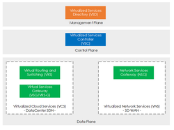
Nuage is an SDN platform, that provides a number of products, such as DC-SDN and SD-WAN. Also known as:
- VCS - Virtualized Cloud Services - DC-SDN
- VNS - Virtualized Network Services - SD-WAN
Within this article we will look at a feature within VCS, known as Backhaul VPLS, and its traffic behaviour.
What is VPLS Backhaul?
The VCS dataplane consists of virtual switches on each hypervisor known as VRS's (Virtual Routing Switching). In a nutshell the VRS consists of 2 components:
- Open vSwitch (OVS) - A software-based switch.
- VRS Agent - Receives communication (such as the FIB) from the VSC and programs the OVS.
Backhaul VPLS is a feature that eliminates the need for each VRS being installed with the FBD/Forwarding information for each locally attached subnet, even if there is no VM present within the subnet. This in turn optimizes and reduces overhead on the VRS as the total subnets/VMs increase.
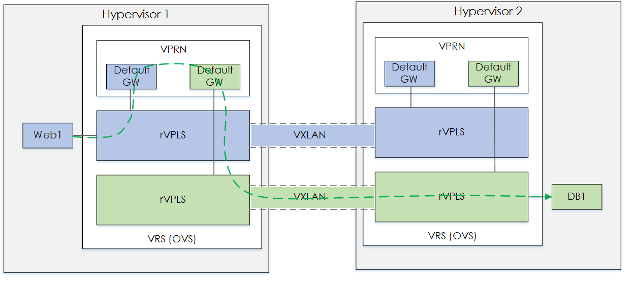
Figure 1 - Without VPLS.
Based on the figure above, as you can see there is no VM on Hyp2. However the VSC would still need to populate and program the VRS FDB's for each rVPLS, even the rVPLS's that do not have any attached VMs - Not Good!
Backhaul VPLS works via the following logic:
If traffic is destined to a remote server for which it does not have a locally attached VM in the subnet. Then send the traffic over the backhaul VPLS (aka VXLAN tunnel).
Note: The Backhaul VPLS does not install any FDB's.
Test Domain
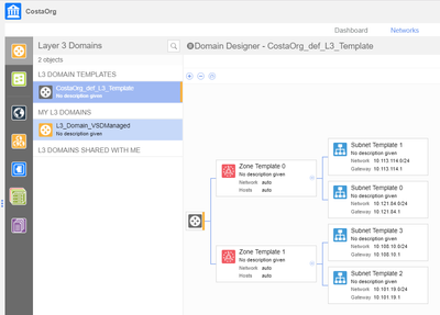
Our tests will be based on the following Layer 3 domain.
Within the domain we will have,
- 2 x Zones - DB and Web
- Each zone we will have a single subnet.
- To begin with we will have:
- Web1 on Hyp1 running
- DB1 on Hyp2 running
Figure 2 - Test Domain.
For reference our IPs will be:
| Device | Hyp | IP |
|---|---|---|
| Web1 | Hypervisor 1 | 10.30.1.180 |
| DB1 | Hypervisor 2 | 10.60.1.154 |
Tests
Ping WEB1-HYP1 to DB1-HYP2
Our first test we will be based on confirming the path of the traffic when pinging DB1 from Web1.
Let us go through the steps.
Send ICMP
Issue an ICMP ping to DB1 from Web1.
Confirm Backhaul VNI
Next we need to confirm the VNI of the backhaul VPLS.
This is done by first getting our VPRN number based on our enterprise and domain name.
*A:vsc1-vsp# show vswitch-controller vports type vm enterprise "Acme" domain "DomainTest"

===============================================================================
Virtual Port Table
===============================================================================
VP Name                 VM Name                 VPRN       EVPN       Multicast
  VP IP Address           MacAddress                                  Channel
                                                                      Map
-------------------------------------------------------------------------------
va-192.168.10.103/1/891 Acme-Web1               1793414612 1304403452 Disabled
  10.30.1.180/24          f0:00:a4:27:79:69
va-192.168.10.104/1/639 Acme-DB1                1793414612 1137663038 Disabled
  10.60.1.154/24          f0:00:12:96:fe:a6
-------------------------------------------------------------------------------
No. of virtual ports: 2
===============================================================================
Next, we obtain the service id of our backhaul based on our VPRN. Like so,
*A:vsc1-vsp# show service id 1793414612 base
...
-------------------------------------------------------------------------------
Service Access & Destination Points
-------------------------------------------------------------------------------
Identifier                               Type         AdmMTU  OprMTU  Adm  Opr
-------------------------------------------------------------------------------
vpls:backhaul-evpn1190836926             rvpls        0       1500    Up   Up
vpls:evpn1137663038                      rvpls        0       1500    Up   Up
vpls:evpn1304403452                      rvpls        0       1500    Up   Up
===============================================================================
With the backhaul service id we can now obtain the VNI,
*A:vsc1-vsp# show service id "backhaul-evpn1190836926" base  | match Vxlan
Vxlan Tenant ID   : 12118425
However, we will also need this in HEX. So this is converted to HEX, which provides us with a VNI of 0xb8e999.
TIP: A recommendation for calculating HEX, is to use the Windows calculator and select programmer mode.
Dump OVS Flows
Now that we have the VNI of our backhaul VXLAN, let us see where our traffic is going.
To do this we will dump the flows of the OVS switch for HYP1.
*A:vsc1-vsp# tools vswitch 192.168.10.103 command "ovs-dpctl dump-flows"
...
skb_priority(0),in_port(36),eth(src=f0:00:a4:27:79:69,dst=68:54:ed:00:e1:be),eth_type(0x0800),ipv4(src=10.30.1.180,dst=10.60.1.154,proto=1,tos=0,ttl=64,frag=no),icmp(type=8,code=0), packets:379, bytes:37142, used:0.987s, actions:set(tunnel(tun_id=0xb8e999,src=0.0.0.0,dst=192.168.10.104,tos=0x0,ttl=64,flags(key))),set(eth(src=0c:c4:7a:6b:98:85,dst=00:00:c0:a8:0a:68)),set(ipv4(src=10.30.1.180,dst=10.60.1.154,proto=1,tos=0,ttl=63,frag=no)),8

skb_priority(0),tunnel(tun_id=0xb8e999/0xffffffffffffffff,src=192.168.10.104/255.255.255.255,dst=192.168.10.103/255.255.255.255,tos=0/0xff,ttl=64/0xff,flags(key)),in_port(8),skb_mark(0),eth(src=0c:c4:7a:6b:96:05,dst=00:00:c0:a8:0a:67),eth_type(0x0800),ipv4(src=10.60.1.154,dst=10.30.1.180,proto=1,tos=0,ttl=63,frag=no), packets:379, bytes:37142, used:0.987s, actions:set(eth(src=68:54:ed:00:e1:be,dst=f0:00:a4:27:79:69)),set(ipv4(src=10.60.1.154,dst=10.30.1.180,proto=1,tos=0,ttl=62,frag=no)),36
As you can see we can see the packets to and from Web1/DB1 for ICMP is using tun_id=0xb8e999, aka the backhaul VXLAN tunnel.
Below shows a topology of the traffic flow,
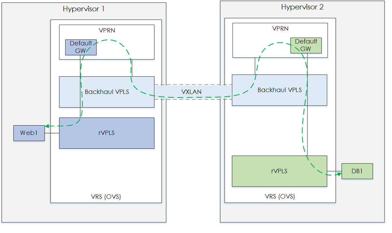
Figure 3 - WEB1-HYP1 to DB1-HYP2.
Create DB2-HYP1
Next, let us create a new VM on Hyp1 - DB2.
We will run another ping and confirm the traffic path.
Send ICMP
Issue an ICMP ping to DB1 (Hyp2) from Web1 (Hyp1).
Dump OVS Flows
Again, we dump the OVS flows. From the flows we see:
*A:vsc1-vsp# tools vswitch 192.168.10.103 command "ovs-dpctl dump-flows"
skb_priority(0),tunnel(tun_id=0xb8e999/0xffffffffffffffff,src=192.168.10.104/255.255.255.255,dst=192.168.10.103/255.255.255.255,tos=0/0xff,ttl=64/0xff,flags(key)),in_port(8),skb_mark(0),eth(src=0c:c4:7a:6b:96:05,dst=00:00:c0:a8:0a:67),eth_type(0x0800),ipv4(src=10.60.1.154,dst=10.30.1.180,proto=1,tos=0,ttl=63,frag=no), packets:33, bytes:3234, used:0.256s, actions:set(eth(src=68:54:ed:00:e1:be,dst=f0:00:a4:27:79:69)),set(ipv4(src=10.60.1.154,dst=10.30.1.180,proto=1,tos=0,ttl=62,frag=no)),36

skb_priority(0),in_port(36),eth(src=f0:00:a4:27:79:69,dst=68:54:ed:00:e1:be),eth_type(0x0800),ipv4(src=10.30.1.180,dst=10.60.1.154,proto=1,tos=0,ttl=64,frag=no), packets:33, bytes:3234, used:0.257s, actions:set(tunnel(tun_id=0xf456ff,src=0.0.0.0,dst=192.168.10.104,tos=0x0,ttl=64,flags(key))),set(eth(src=68:54:ed:00:5f:30,dst=f0:00:12:96:fe:a6)),set(ipv4(src=10.30.1.180,dst=10.60.1.154,proto=1,tos=0,ttl=63,frag=no)),8
From this we can see the ICMP response going over the VXLAN tunnel.
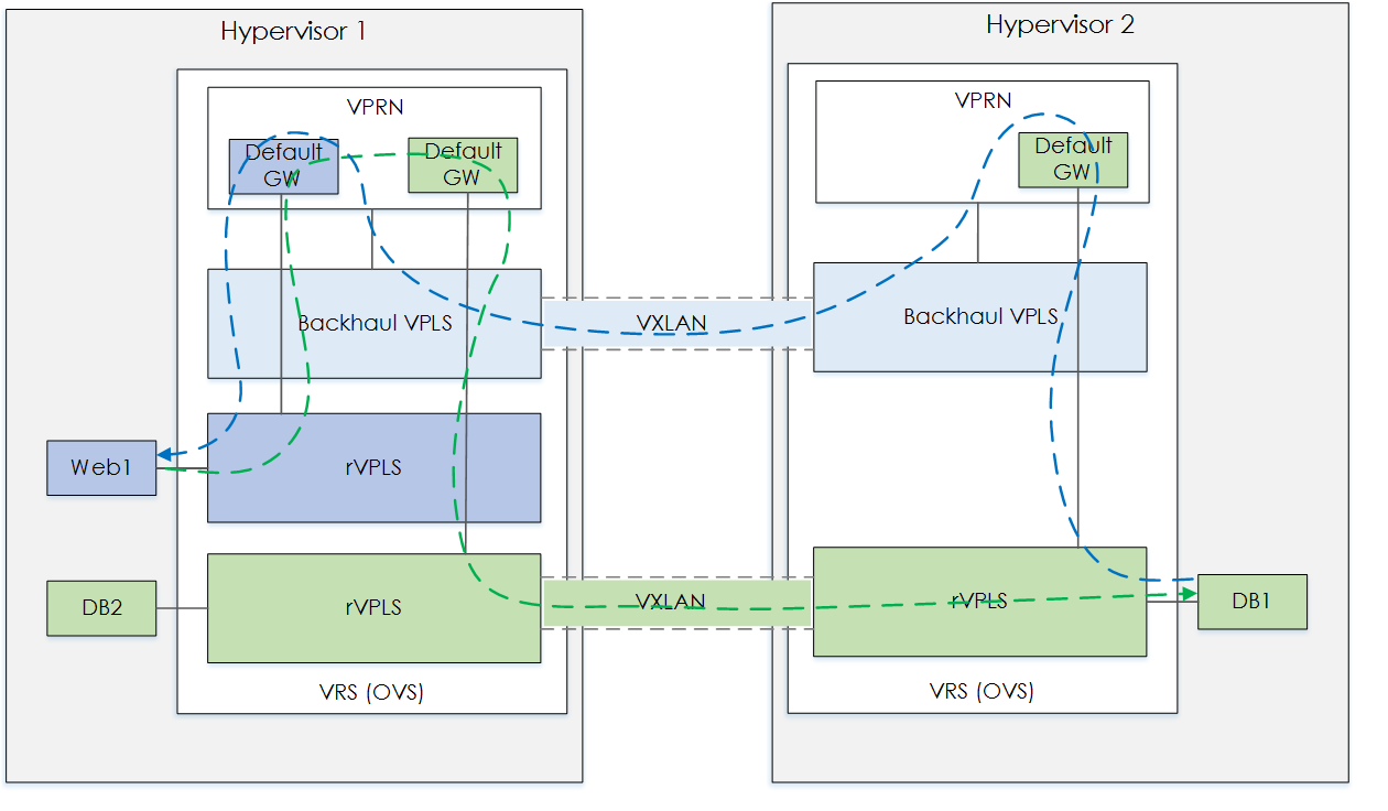
Figure 4 - Add DB2-HYP1 VM.
But the ICMP request is going over tun_id=0xf456ff. This should be the DB Zone VXLAN. Lets check.
Confirm VNI
First we convert tun_id=0xf456ff to decmial, which is - 16013055
Then we confirm the EVPN id for the DB zone. Like so,
*A:vsc1-vsp>show>service>id# show vswitch-controller vports type vm enterprise "Acme" domain "DomainTest" | match expression "EVPN|DB"
VP Name                 VM Name                 VPRN       EVPN       Multicast
va-192.168.10.103/1/912 Acme-DB2                1793414612 1137663038 Disabled
va-192.168.10.104/1/639 Acme-DB1                1793414612 1137663038 Disabled
Finally we can look up the Tunnel VNI, using the EVPN id. Like so.
*A:vsc1-vsp>show>service>id# show service id evpn1137663038 base | match Vxlan
Vxlan Tenant ID   : 16013055
As expected, this confirms our thought on the traffic path. This flow makes sense when you think about it, as the VRS has a VXLAN for the zone, which is uses to reach the DB zone on hyp2. However, from hyp2 there is no VXLAN for the packet to take in order to get to the Web zone.
Create DB2-HYP1
Now, we create Web2 on Hyp2. Let's go...
Send ICMP
Issue an ICMP ping to DB1 (Hyp2) from Web1 (Hyp1).
Dump OVS Flows
*A:vsc1-vsp# tools vswitch 192.168.10.103 command "ovs-dpctl dump-flows"
skb_priority(0),in_port(36),eth(src=f0:00:a4:27:79:69,dst=68:54:ed:00:e1:be),eth_type(0x0800),ipv4(src=10.30.1.180,dst=10.60.1.154,proto=1,tos=0,ttl=64,frag=no), packets:523, bytes:51254, used:0.573s, actions:set(tunnel(tun_id=0xf456ff,src=0.0.0.0,dst=192.168.10.104,tos=0x0,ttl=64,flags(key))),set(eth(src=68:54:ed:00:5f:30,dst=f0:00:12:96:fe:a6)),set(ipv4(src=10.30.1.180,dst=10.60.1.154,proto=1,tos=0,ttl=63,frag=no)),8

skb_priority(0),tunnel(tun_id=0xed9e3e/0xffffffffffffffff,src=192.168.10.104/255.255.255.255,dst=192.168.10.103/255.255.255.255,tos=0/0xff,ttl=64/0xff,flags(key)),in_port(8),skb_mark(0),eth(src=68:54:ed:00:e1:be,dst=f0:00:a4:27:79:69),eth_type(0x0800),ipv4(src=10.60.1.154/255.255.255.255,dst=10.30.1.180/255.255.255.255,proto=1/0,tos=0/0,ttl=63/0,frag=no/0xff), packets:35, bytes:3430, used:0.573s, actions:36
Now we can see the return traffic going over tunnel id 0xed9e3e, decimal conversion 15572542. This should be the Web Zone VXLAN tunnel. Lets confirm,
Confirm VNI
*A:vsc1-vsp>show>service>id# show vswitch-controller vports type vm enterprise "Acme" domain "DomainTest" | match expression "EVPN|Web"
VP Name                 VM Name                 VPRN       EVPN       Multicast
va-192.168.10.103/1/891 Acme-Web1               1793414612 1304403452 Disabled
va-192.168.10.104/1/646 Acme-Web2               1793414612 1304403452 Disabled

*A:vsc1-vsp>show>service>id# show service id "evpn1304403452" base | match Vxlan
Vxlan Tenant ID   : 15572542
And there it is VNI 15572542, confirming that the ICMP response, i.e the return traffic is going over the Web Zone VXLAN tunnel. As shown below,
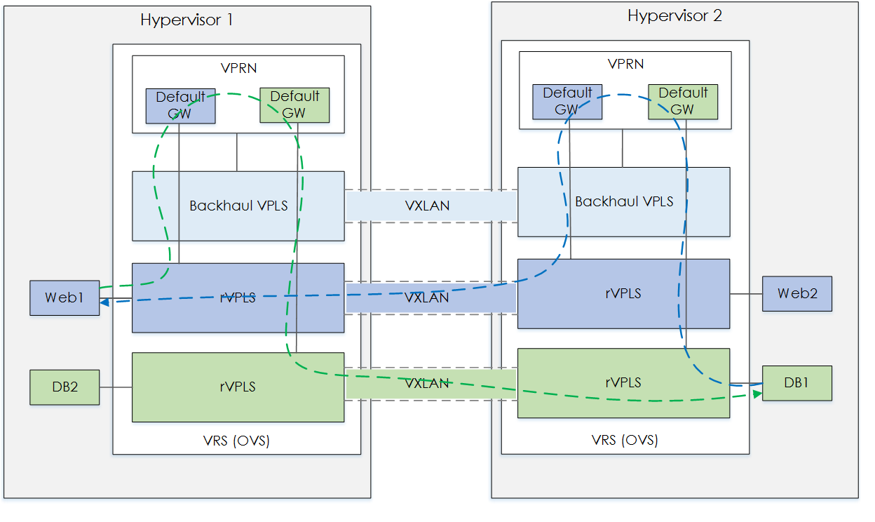
Figure 5 - Add DB2-HYP1 VM.
Outro
That concludes our look into backhaul VPLS traffic behaviour. We have seen backhaul VPLS in action, how it operates based on the various VM placement scernios and the dynamic nature of the Nuage dataplane in order to optimize VRS.


