Introduction
Within this article, we will look at the history of spine and leaf. We will first look at the problems seen with traditional networks, the background to the spine and leaf architectures aka Clos, and then finally look at how this fits into the spine and leaf architectures of today.
The Problem
Traditional datacenter networks historically were based upon a 3 tier architecture - the core, the aggregation and access layer. As shown below:
- Core - Responsible for transmitting large amounts of traffic quickly.
- Aggregation/Distribution - The Distribution layer bridges users to the core layer. In most deployments, Default Gateways for all the VLANs reside at the Distribution layer.[1]
- Access - Contains the ToR switches, which are connected to the end hosts such as servers.
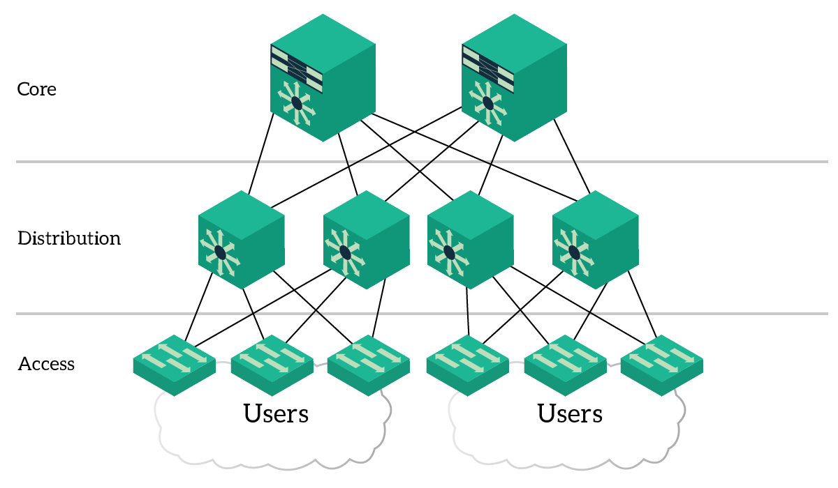
Figure 1 - 3-Tier Architecture.[2]
The key problem with the traditional 3-Tier architecture is that each layer provides a different level of oversubscription i.e 2 users sending traffic over the same distribution switch, to users having to transverse the core will also experience different levels of oversubscription, aka bandwidth. To combat this the 3-Tier design needed to be moved to a 2-Tier model, something that wasn't previously possible due switch limitations due to port density and throughput limits. Which, with today's modern datacenter switches, no longer presents an issue.
Clos
In 1952, Charles Clos formalized the concept of a type of multistage circuit switching network, known as Clos. At the time voice exchanges were hugely expensive. Charles Clos realized that voice exchanges could be build based upon combining multiple small crossbars in sequence.[3] As shown below.
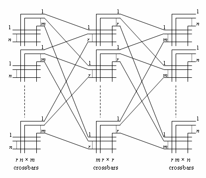
Figure 2 - Clos Architecture.[4]
Clos is based on the following: n input ports upon a single crossbar and m output ports equates to the oversubscription ratio. The output ports are then connected to each central crossbar, and so on. Therefore, the result - one level of oversubscription and a non-oversubscribed core.
Spine and Leaf - 3 Stage Clos
The Clos architecture is not only useful within the voice exchanges of the past. Clos can be used for data networking too, in fact, Clos architectures have been used internally within fabric switches for a number of years.
Let's dive into some more detail. So based on the Clos diagram above, and based on only 2 levels of crossbars, we can produce a 3 stage Clos. By 3 stage I mean that the leaf's are stage 1 and 3 and the spine is stage 2.
Furthermore, each leaf is connected to each spine, with there being no connectivity between spines.
ECMP is then used to equally distribute the traffic across the spine and leaf fabric.
With regards to oversubscription:
| Fabric Point | Description | Oversubscription |
|---|---|---|
| Ingress | Leaf ingress. Traffic from servers to the core. | Oversubscription |
| Egress | Leaf egress. Traffic from core to servers. | No oversubscription |
| Core | Spine ingress/egress. Traffic from leaf's | No oversubscription |
For example:
Let us take a very simple example.
- We have a 48 x 10Gb switch with 4 x 40Gb uplinks.
- This provides each switch with a 3:1 oversubscription ratio. I.e 480Gb down and 160Gb up to the core.
- Each 40Gb link is connected to a single spine.
- Therefore every end host can reach every other end host via 3 stages (leaf, spine, leaf), no matter where they are.
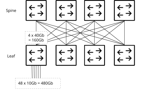
Figure 3 - Spine and leaf - 3 stage.
And therefore by using the multistage concept of Clos, with todays network switches, we can build spine and leaf fabrics that overcome the challenges, seen with historic network architectures.
References
"Cisco Three-Tier Architecture Explained - ICTShore.com." 27 Apr. 2017, https://www.ictshore.com/free-ccna-course/three-tier-architecture/. Accessed 4 Jul. 2018. ↩︎
"Cisco Three Tier Architecture Explained - ICTShore.com." 27 Apr. 2017, https://www.ictshore.com/free-ccna-course/three-tier-architecture/. Accessed 4 Jul. 2018. ↩︎
"www.ipSpace.net." https://www.ipspace.net/. Accessed 4 Jul. 2018. ↩︎
"Clos network - Wikipedia." https://en.wikipedia.org/wiki/Clos_network. Accessed 5 Jul. 2018. ↩︎


